Getting started
There’s a few things to do before controlling a brushless motor with the Dagor Controller. Make sure to read this section carefully before trying to use the controller.
Step 1. Materials
The first step is to collect all the necessary materials together:
- Dagor Controller - Alpha
- Diametrically polarized magnet (included with controller)
- Brushless motor
- Motor/ controller fixture
- Adequate power source
- USB to TTL converter
- Connectors (optional)
Step 2. The motor
This section includes the steps to prepare to use a particular brushless motor. Visit the BLDC motor’s page to learn more about the type of brushless motors and their typical uses to aid in the selection of an adequate motor for a particular project.
2.1 Phase resistance:
If there is no information regarding the phase resistance of the motor from the manufacturer measure the phase resistance with a multimeter. It doesn’t matter if the multimeter isn’t extremely precise, what matters is getting a rough estimate of its resistance. Usually, gimbal brushless motors have a phase resistance of around or above 10 ohms, which is considered a big resistance, and drone motors usually have a resistance bellow 1 ohm, which is considered a small resistance. Write down the phase resistance as it will be needed later.
2.2 Pole pair number
Usually, the manufacturer of the motor will rate the motor something similar to this: 24N22P, where N means the number of coils and P means the number of poles (magnets). To know the number of pole pairs divide P (poles) by two, in the case of this example 22/2 = 11 pole pairs. If the manufacturer fails to provide this rating and if the magnets are exposed, the pole pair number can be found by counting the magnets on the motor’s rotor and dividing by two.
2.3 Attaching the magnet
The Dagor Controller has an on-board magnetic sensor to measure the angular position of the motor’s rotor, this is critical for the FOC (field oriented control) algorithm. At this point the magnet provided with the controller has to be firmly attached to the motor’s rotor. There are two easy ways to do this: design and 3D print a base for the magnet and hot glue it to the motor’s shaft (very easy to remove) or super glue the magnet directly to the motor’s shaft (not so easy to remove).
Step 3. Arduino IDE and SimpleFOC
The firmware was developed for the Arduino development environment and is powered by the SimpleFOC project. Setting up the Arduino IDE properly will assure an effortless way to work on a project with the Dagor Controller. Follow the installation instructions to install the SimpleFOC library and follow the ESP32 microcontroller set-up page to configure the Arduino IDE to support ESP32 boards. It is recommended to update the board’s firmware before connecting the motor to the board.
Step 4. Flashing the firmware
This section includes the relevant steps to update the firmware on a brand new Dagor Controller.
4.1 Powering-on the Dagor Controller
To power on the Dagor Controller connect 5 - 24V to the input bus. Positive voltage and 0V are marked on the board as VD and GND. The first time the controller is powered on the YELLOW LED will start blinking. This is to show that the controller is working and ready for a firmware update.
| WARNING |
|---|
| Make sure the supplied voltage is connected correctly, there is NO reverse voltage protection! |
| Avoid touching the components while the board is powered, failing to do so could fatally damage the controller. |
4.2 Downloading the firmware and changing user parameters
Download the most recent firmware version from the Github repository and open it on the Arduino IDE. Visit the firmware section to learn about the firmware structure and version name.
Given each individual set-up there’s a few parameters that must be changed in the firmware. By this point the pole pair number, the phase resistance, the power supply voltage should be known. Visit the user parameters section to learn how to update these parameters in the firmware. Compile the code to make sure there will be no errors moving forward.
4.3 Controller flash mode
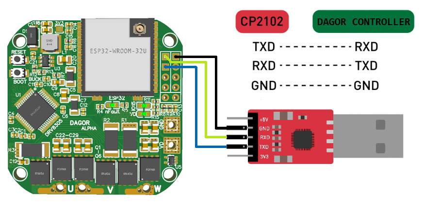
It is required a USB to TTL adapter to flash the Dagor controller; it is recommended to use the CP2102 module. Solder (optionally) any type of headers style to the board to be able to easily connect and disconnect the module. Once the adapter is connected to the board (as shown in the picture bellow) and the board is powered, to put the Dagor controller in flash mode press and hold the _Reset_ Button, press once the _Boot_ Button and then release the _Reset_ Button. If done correctly the Serial monitor of the Arduino IDE should print that the board is waiting for download. After updating the firmware with the correct parameters (section 4.2), press the upload button on the Arduino IDE and the ESP32 will begin flashing, after it’s done press the _Reset_ Button once and the code should start running.
Step 5. Motor and controller fixture
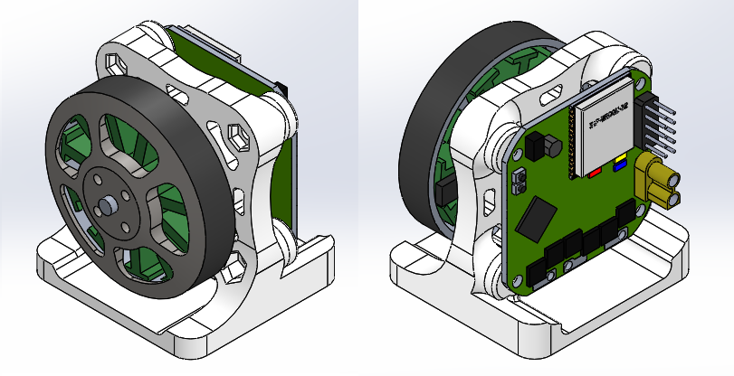
The Dagor controller has to be firmly attached to the motor’s stator, making sure that the center of the magnet (section 2.3) is centered with the board’s magnetic sensor. One easy way to do this is by designing and 3D printing a fixture (or test station) that fixes together a motor (with its magnet) and a controller. Here you can find a CAD to use as reference for a 3D printed fixture, like shown in the picture bellow.
Step 6. Testing
The only thing left to do is test the set-up and tune the controller.
6.1 Connecting everything
Connect the Dagor controller to the motor and the USB to TTL module, power the controller and the motor will start position controlling the motor. On power on the first thing that will happen is that the motor will run a calibration before going into position control mode, make sure you let the calibration run successfully before touching the motor’s rotor. The calibration should look like the following: the motor moves a few degrees in a direction and a few degrees back in the other direction; if there is no movement the current limit or the phase resistance is set too low, one of the two should be increased and upload the firmware again, if the red LED turns on the current limit or the phase resistance is set too high, one of the two should be decreased and upload the firmware again.
A successful calibration will look something like this:

If the controller is very badly tuned (as is expected) the position control might work very badly and tuning will be needed. Make sure to start with a very modest voltage limit so that the response isn’t very bad while tuning the controller’s parameters.
6.2 Tuning the controller
Tuning the controller is essential to obtain the desired response out of the motors movements, avoid oscillations and avoid vibrations. The Serial monitor is used to tune the controller by sending commands to it. These commands are implemented in the SimpleFOC Commander interface.
Please refer to the Commander interface page to learn about all the different commands and please visit the motion control implementation to learn about the control loops and control theory.
6.3 Share
Share with us your set-up! SimpleFOC forums